How to build your own optical sensor
Equipment
- basic soldering kit
- Soldering iron
- Soldering tin
- Soldering mat
- Wires with 3 different colors
- Shrink tubes
- 100k ohm resistor
- photoresistor(LDR)
- GL5528 LDR or GL5537 LDR
- 3v DC power supply of your choice (any of the following options would work fine)
- 2x AAA batteries in parallel
- 3v GPIO pins of the OpenBCI board
- 3v LiPo battery
Circuit design concept
The circuit is a simple voltage divider, consisting of a number resistor and a LDR. The LDR’s resistance is a function of light exposure. The resistance is reciprocally proportional to light intensity. Thus, by exposing the LDR to any of the visual noise tags (e.g. the flickering buttons on the screen of your computer) The output voltage mimics the behavior of the flickering pattern.
Steps to build the sensor
Solder the resistor and the LDR together.
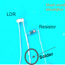
Solder the red, blue and black wires as demonstrated below.
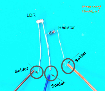
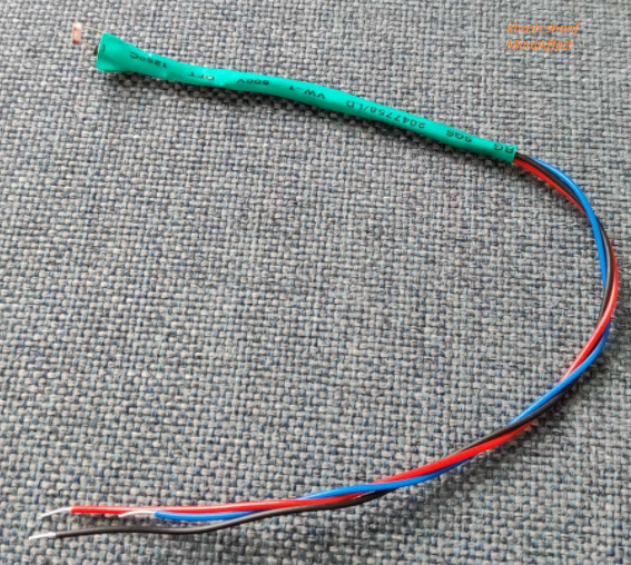
Add shrink tubes at the soldering locations and apply heat to insulate the connections.
You have yourself an optical sensor!
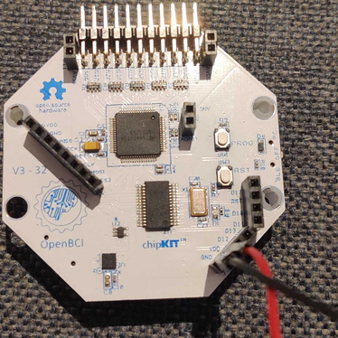
How to use this sensor with an OpenBCI board
First, the sensor must be connected to the OpenBCI board as described below.
- Red wire –> vDD OpenBCI board.
- Blue wire –> signal pin of openbci. You can use any free channel as your signal pin.
- Channels 1-8 for the openBCI cyton board.
- Channels 1-4 for the openBCI ganglion board.
set the board to bipolar mode
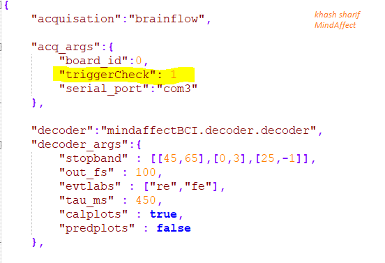
- For the cyton board, go to pymindaffectBCI/mindaffectBCI directory and open the online_bci.json file. Next, enable trigger check by adding the highlighted line. (don’t forget to save the file afterwards)
For the ganglion board, follow this guide and set the switches to DOWN position.
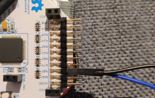
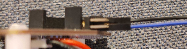
Then the blue wire should be connected to
- The lower pin of cyton channel of choice (by default this is set to channel 8)
- The upper pin of ganglion channel of choice
The black wire should be connected to the GND gpio pin and the ground signal pin (in bipolar mode, the lower pin of ganglion and the upper pin of cyton)
Testing the functionality
- To quickly test the optical sesnor
- Connect the OpenBCI to your PC and power up the board
- Connect the Optical sensor to the OpenBCI board (as discussed above)
- run the MindaffectBCI program as usual
- start the MindaffectBCI presentation
- perform calibration by placing the optical sesnor in front of the cued buttons
- go to prediction mode. The system should detect any button that is put in front of the optical sensor (as demonstarted below)