Raspberry pi GPIO
Raspberry pi GPIO for Presentation
Mindaffect BCI is not limited to a screen based presentation. For example, physical lights and tactile vibrators can be used as means of stimulus. But first we need to connect our software to the desired hardware device (e.g. a lamp, LED, tactile vibrator). The software/hardware interfacing is done using GPIO. GPIO is a standard interface used to connect microcontrollers to other electronic devices. It can be used with sensors, diodes, displays, and System-on-Chip modules. For demonstration purposes we use a raspberry pi(Rpi) board. Any Rpi board with wireless connectivity is compatible with our software. In the rest of this section we discuss how to implement your physical presentation system of choice using Rpi’s GPIO.
You will need
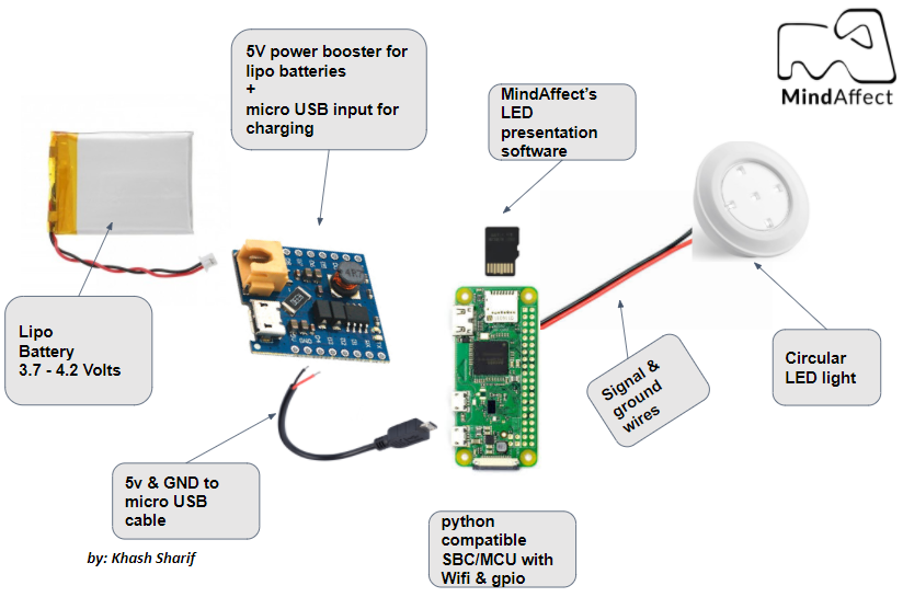
- Rpi zero W
- microSD card
- Lipo battery
- Power Circuit (DC-DC boost convertor)
- LED lights
- Enclosure
- Tools:
- Soldering equipment
- Hot glue equipment
Design concept
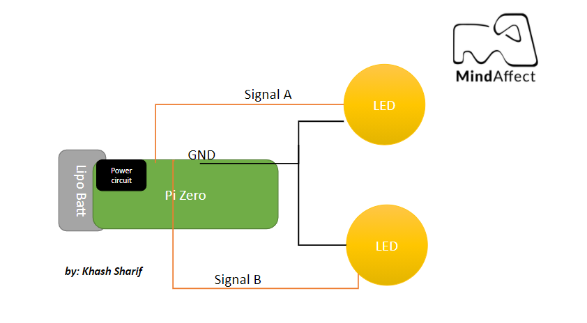
The BCI stimulus is represented by binary codes. To transfer that into a physical flickering pattern the LED/lamp/tactile vibrator will be ON when the code value is 1 and will be toggled to OFF when the code is value is 0. For example: Code 1011010 is represented by ON-OFF-ON for twice as long-OFF-ON-OFF. A raspberry pi zero W is used for demonstration purposes. Below you can see a schematic diagram of how the electronic hardware looks like for a 2 button presentation module Where one LED plays the binary pattern from code A and the other one plays the pattern from code B. It is up to you to decide how many LEDs you would like to use.
Software setup
The board needs to be programmed with the MindAffect GPIO software build on top of gpizero library. To do so, follow the steps below.
- Follow this guide to install the Raspbian OS and enable SSH on your Rpi.
- Now, connect to the raspberry pi via SSH and run the following command in the terminal
- sudo apt-get install git default-jre default-jdk python3 build-essential cli-common xterm ant gradle
- Clone the pymindAffectBCI repository by using the following command
- git clone https://github.com/mindaffect/pymindaffectBCI
- Install the necessary bits to your local python path:
- change to the directory where you cloned the repository.
- Add this module to the python path, and install dependencies
- python3 -m pip install -e .
- If you would like to configure the Rpi such that the MindAffect GPIO software automatically starts on boot, do the following:
- Open the autostart script by running the following command
- Sudo nano /etc/xdg/lxsession/LXDE-pi/autostart
- Add the following line to the autostart file
- python3 -m mindaffectBCI.examples.presentation.rpigpio
- Press ctrl+x, then press Y and then Enter to save changes.
- The changes will take effect after a reboot.
- Make sure you are connected to the same WiFi network that is used by the machine running the MindAffectBCI software.
- The rpigpio python script uses GPIO pins 2,3,4 by default. You can customize it to your liking.
- Allright, the software is set up. Next, the hardware needs to be assembled.
Directions for setting up a minimum presentation hardware
- Connect the + pins of the LEDs to the GPIO pins
- By default pins 2,3,4 are used in the rpgpio.py script. You don’t have to use all the pins, but you need to inform the software about How many pins are going to be used by the LEDs
Connect the - pins of the LEDS to the GND GPIO pin
- solder the micro USB cable to the power circuit pins
- red wire –> 5v pin
- black wire –> GND pin
Connect the power circuit to the Rpi board.
Caution: If you are not familiar with safety cautions related to LiPo batteries use other safe batteries (such as AA battery packs) or learn how to safely use a LiPO battery. The power circuit & the battery can blow up if you plug in the battery the wrong way. Use at your own risk or choose a safe battery instead. As soon as the battery is connected to the power circuit the Rpi board will boot
- To shutdown the system, you can connect to the Rpi board via SSH and run the following command:
- Sudo shutdown -h now
- Then you can safely unplug the battery after the RPi’s green lights turn off
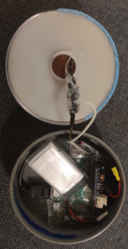
Place all the assembled parts in the enclosure and insulator the electronics using hot glue.
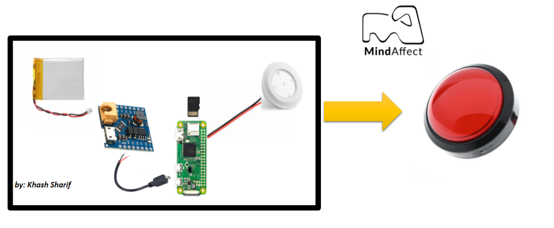
The final LED button looks like this:

To run the full demo
- On your host computer, go to the directory of pymindaffectBCI/mindaffectBCI . Open the online_bci.json file and set the presentation argument to None
- “presentation”:”None”
Now plug in the battery to the power circuit of the LED button and close the enclosure.
Make sure your host computer and the LED button are connected to the same network
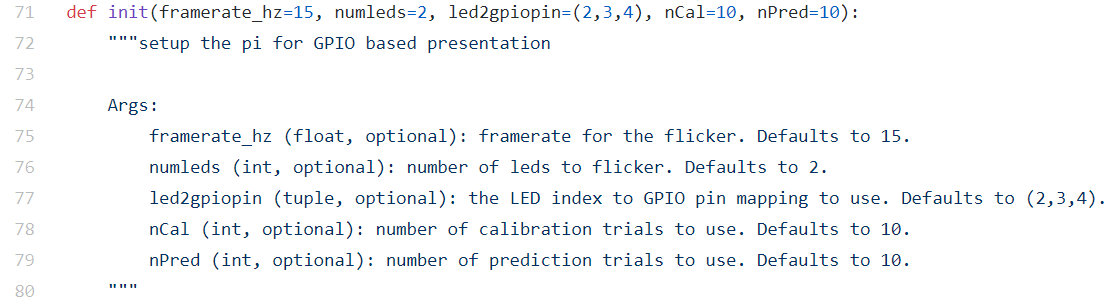
- The LED button should connect to the host computer and the presentation starts automatically and runs using the default arguments (see the code snippet below). You can set the following arguments in the rpigpio.py script:
Number of calibration and prediction trials
Number of LEDs
The LED to GPIO pin mapping
Speed of stimulus in Hz
Here’s how a one button LED presentation looks like (the LED button stays ON for a while when it is selected by the user’s brain response)
And a two button system looks like
RPI GPIO for control
You can control a physical device using MindAffect’s output module and a board with GPIO. For demonstration purposes we use GPIO pins of a raspberry pi board to control other physical devices.